
.png)
.png)
.png)
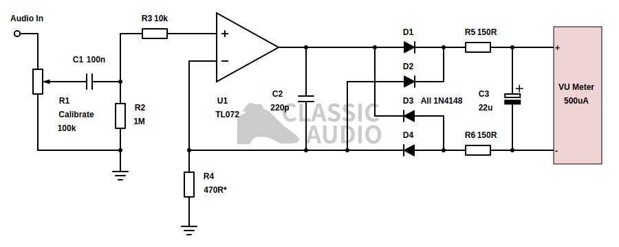
I used everything in the schematic from C2 to the meter. Everything else on the schematic was provided on the ne5532 board.
How much distortion is acceptable is a personal question each engineer must answer for themselves. Or, you could use a buffer, such as an opamp. By buffering the meters from the loudspeakers, you can get the best of both worlds. Note, that with the buffer, you still need the diode bridge to get the meter working. Also, You can wire up a "Thru" patch to the inputs of the meters and have no discernable penalty to the audio. This is great a solution and should you need to run your meters on your main stereo bus, you should add the "Thru" jacks into your meter build.
How much distortion is acceptable is a personal question each engineer must answer for themselves. Or, you could use a buffer, such as an opamp. By buffering the meters from the loudspeakers, you can get the best of both worlds. Note, that with the buffer, you still need the diode bridge to get the meter working. Also, You can wire up a "Thru" patch to the inputs of the meters and have no discernable penalty to the audio. This is great a solution and should you need to run your meters on your main stereo bus, you should add the "Thru" jacks into your meter build.
However, since I have plenty of outputs to spare, I simply run a second stereo bus to another set of outputs on my recording interface. So, my meters just have an input, and they work great.
The Audio path looks like this: Input jacks> 100k Pots> 5532 board> Diode board/cap>Meter +. (Note: Ground to audio input ground)

So now my needles are jumping, I needed to get them glowing. Since Teac used 8v lamps in their meters, I knew I needed to get there without spending too much hard earned cash, or valuable time. Enter the $15 variable voltage regulator. With a simple input of 12v, AC or DC, I could get to 8 volts, or even a little less to increase the life of the bulbs.
.png) The Power supplies A &B look like this: A. DC 12v wallwart> 5532 board. B. DC 12V> Adjustable power regulator board (set to 7 or 8 volts) > 8 volt meter lamps.
The Power supplies A &B look like this: A. DC 12v wallwart> 5532 board. B. DC 12V> Adjustable power regulator board (set to 7 or 8 volts) > 8 volt meter lamps.
.png)
.png) I also made a case out of mahogany wood to make my meters "pop!"
I also made a case out of mahogany wood to make my meters "pop!"

So now my needles are jumping, I needed to get them glowing. Since Teac used 8v lamps in their meters, I knew I needed to get there without spending too much hard earned cash, or valuable time. Enter the $15 variable voltage regulator. With a simple input of 12v, AC or DC, I could get to 8 volts, or even a little less to increase the life of the bulbs.
.png)
.png)
Tests of the voltage regulator from 24vdc down to 7.41vdc.
.png)
All that was left to do was calibrate the meters from a 1k sine wave at 1.228v.
.png)
When the input pots are set to "0" you're good to go.
.png)
.png)
And that's pretty much it! Plug in your inputs and select your program material- you're ready to "see" what you're hearing.